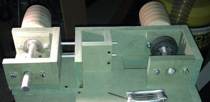
I initially started designing my belt sander around some cheap and cheerful belts I picked up from B&Q that were in a discount bin. As per my requirement for easy belt changing I have stuck the main belt wheels out the side of the machine. The two red things that look like bolts are in fact bolts and the idea is that by turning them separately it’s possible to adjust both the tracking and the tension of the belt. The additional shaft sticking out the side is for a disc sander attachment.
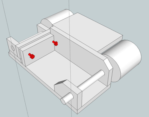
This shot of the back of the machine shows how the idler shaft pivots around a bolt that runs down through the main base plate.
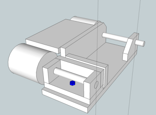
The blue bolt acts as a pivot and constrains the idler wheel so that it can only move along one axis and rotate in one plane.
As soon as I’d finished this design I felt that there were a number of problems with it. The belt wheels were a whopping 100mm diameter which I felt was too large. The tensioning and tracking system (red bolts) while clever would probably turn out to be very tricky to operate. The belts have some spring in them but not much which would probably mean I would end up constantly tightening one bolt and slackening off the other till eventually reaching the correct balance.
Other than that though I was fairly happy with the basic design. The way the belt would be fitted allowed for easy replacements and there was a stubby shaft for a disk sander attachment. Over the all the design felt a bit large though and it doesn’t even have the motor installed yet.
Little did I know there was actually a fairly sizeable design flaw approaching from stage right…