
With the inrush / soft start designed and most of the parts ordered my mind turned to the other components I’m going to need to finish the case.
One of my goals with this build is to have the electrical cabinet easy to separate from the rest of the CNC machine. I’m fairly sure that if the machine works as well as I hope it will then it’ll remain in one place most of the time but if I do have to move it I really don’t want to be having to unwire steppers etc. Adding connectors does however introduce new failure points into the system so the choice of connector is important. In particular if a stepper plug coming loose it will likely damage the drive and the same is almost certainly true of the VFD. Additionally I don’t want the e-stop and other circuits coming loose and triggering emergency stops or ruining a work piece so some sort of locking connector is in order. The steppers draw about 4.2A when going flat out so a connector that can handle 5A or more is needed for those connections. The VFD manual gives the maximum output as 10A but I’ve heard that the high frequency signals cause premature failure of the connection so a higher rated connector is probably a better choice there. Finally the body needs to be metal so that it can be connected to the cable shielding. Before I get into choosing the connectors though a word on earthing.
Earthing
There is, in my opinion, a lot of unjustified worry about earthing CNC machines and introducing interference. Incorrect earthing can certainly cause problems but as long as one simple rule is followed there shouldn’t be a problem in the majority of cases. Most problems stem from overly enthusiastic earthing where everything that should be earthed is connected via multiple different paths back to earth. The result of this random earthing style is invariably an earth or ground loop (another explanation) which can cause interference. To cut a long story short if you create a loop of conductive material (e.g. wire, metal cabinet, screening on a cable) then you risk inducing current flow in that loop. That current flow can then induce current on other cables which results in missed / additional steps, unwanted emergency stops and all manner of other weird behaviour. The most common way to cause a problem is to wire the screen on a stepper or sensor cable to earth at both the cabinet and machine ends. The steppers tend to handle noise introduced this way fairly well as the voltages are high (around 70V typically) but the sensor voltages are much lower (sometimes as low as 5V) and so it’s not inconceivable that a little induced current from a ground loop could turn that +5V into 0V and trigger an e-stop.
The one simple rule to follow is to wire in a star pattern something like this:
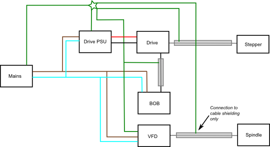
Don’t copy this diagram like it’s the last word in CNC wiring! The idea of this diagram is to show a pattern that will work. Notice that there are no switches or fuses anywhere – you will want some! The BOB I’m using is powered straight from the mains and doesn’t have a earth point directly but the case is earthed and the BOB is screwed to the case so it will probably be getting an earth that way, you may or may not have a separate power supply for your BOB if you do it should be earthed. Note also how the shield on any shielded cables is connected to earth at only one and where the cable exits the machine (e.g. to run to a stepper) it is earthed at the controller end. If the cable run includes a connector then the connector should have a metal body with some way to connect the shield to the metal body of the connector. Creating a Y in the earth cable is fine (because there’s no loop) but if it can be avoided it should be. I have a Y in the earh cable running from the VFD and the shield on the signal cable. It’s very unlikely I would wire it this way in real life as the parts would be physically well separated but it was simpler to show it that way in the diagram.
While researching this article I came across a few things that I’d never even considered doing but seem to crop up in conversation on a regular basis. The first is confusion over earth ground (green in the diagram, green and yellow on the cable) and DC common (black). If you get a meter out and measure the potential difference between earth ground and dc common you will often find little or no potential difference but this does not mean they are the same. Many commercial power supplies will bond dc common to earth via a resistor which prevents the dc common from floating to a large potential above earth but that doesn’t mean you should go around connecting neutral to earth as you’ll defeat the bonding in the power supply and risk creating loops. Additionally you should never use the shield on a cable as a return for power or signal and daisy chaining earthing should also be avoided where possible. Essentially you never want a current flowing along anything that is earthed unless there is a fault in the system.
Connectors
I ended up really struggling with the connectors when perhaps it wasn’t necessary. My list of requirements were:
- Greater current handling capability than the part apparently needs on paper. The thinking behind this that I want to minimize contact losses and ensure that any high frequency signals don’t damage the connector. I’ve heard reports that the high frequency and high power produced by the VFD is particularly tough on connectors. My aim is for twice the current handling ability where possible.
- Sockets should be female on the cabinet. The part attached to the cabinet, the socket, must be female since it has potentially dangerous voltages. This might seem like a simple requirement but it proved to be surprisingly difficult. For some reason most aviation style connectors seem to have male sockets.
- The connector must lock or screw together. A connector coming apart while the machine is running is not a something you want to have happen and there’s a slight chance of vibration.
- The connector should have a metal body. The metal body allows for the connection of the wire shield.
After much searching and reading I settled on using the WS series circular connectors from Weipu sing ZZ square flange receptacles and TQ plugs with mechanical clamps. The 5 pin, 20mm variety are rated at 10A with 1.5mm connectors so more than enough for the steppers and they allow me to pass the earth on through (even though it won’t be connected at the stepper). The 4 pin, 20mm variety are good for 25A since they have 2.5mm connectors. This, again, is more than enough for the spindle. You’ll notice in table below that I bought an additional 4 pin connector set for the e-stop circuit. This circuit doesn’t need anything like this size connector but it was the simplest solution as the 5 pin connectors came in lots of seven (five for the steppers, one for the home switches, one for the limit switches)
An alternative for the steppers might have been four or five pin XLR connectors but I wasn’t all that keen. The lock isn’t as robust and the socket protrudes into the case which I didn’t really want. The XLR connectors are also quite long considering their diameter and I think there’s a chance they could get damaged in a workshop environment.
I came across a number of people swearing by DIN connectors for the steppers. The main benefit I can see of DIN connectors is they are cheap as chips if you go for the non-locking variety. The locking variety are quite a bit more expensive and I couldn’t find any that were rated to the sort of current I wanted, typically they were 4A. To be fair 4A would probably be enough as the steppers don’t draw their full load most of the time but I don’t want to spoil the job for a half penny of tar at this stage.
I found some connectors that, apparently, can be make or female in both the plug and the socket. I currently only have the plug that comes with the spindle to play with and that seems to be firmly female – the correct way around in this case. I’ll be having an experiment with one of the stepper plugs to see if I can convert it’s gender. The connectors sold by PMDX look to be pretty much the same as all the others of that variety though and they appear to be firmly males sockets (I pick on PMDX because it’s one of the few places with decent photos of the connectors, see in particular the 4 pin connector).
The other connector I needed was for power into the case. I stupidly thought this would be simple and rushed out to Tool Station and bought a 16A socket. It was only when I offered it up to the cabinet with a big grin on my face that I realized my mistake. What you can easily buy is a 16A (female) outlet what the cabinet needs is a 16A (male) inlet. The reason only becomes obvious when you think about the other part of the connector. If the cabinet is female it means the cable providing the power would have to be male and live exposed pins are never a good idea!
Fortunately you can buy 16A inlets, they seem to be used for caravan hook ups, but almost all of them are angled connectors and the cabinet needs a straight panel connector. Finding one wasn’t actually too difficult, finding one that didn’t cost the earth was a bit trickier. In the end I found one that was a reasonable price but the shipping nearly trebled the bill. The worst price was CEF which quoted me £15 just for the socket!
| Site | Part | Description | Total |
| eBay (sellerbible) | Weipu WS20-4 | Aviation circular connector socket, 4 pin, 25A. Singles, 2 bought – For spindle and e-stop | £7.66 |
| eBay (sellerbible) | Weipu WS20-4 | Aviation circular connector plug, 4 pin, 25A. Singles, 2 bought – For spindle and e-stop | £9.24 |
| AliExpress (JCD (ShenShen) Co Ltd) | Weipu WS20-5 | Aviation circular connector plug and socket, 5 Pin, 10A. Pack of 7 – For steppers, home and limits | £32.28 |
| eBay (sellerbible) | P20K9Q | Aviation circular connector plug and socket, 5 Pin, 25A – Probably won’t get used, maybe for the spindle. | £3.66 |
| eBay (psfpowerandpyroltd) | Famatel 16A Inlet | Famatel 230V 16A 2P+E inlet. | £8.47 |
| £61.31 |
While doing the research for the connectors I realized the wiring plan I had in my head included a potential mistake. There is a shielded cable running from the stepper drive to the back of the connector socket. My plan was originally to earth the shield at the drive end and connect the shield to the socket to continue the earth on up the shield to the stepper. The problem with this plan is that it would create an earth loop though since the cabinet body is earthed and the socket isn’t electrically isolated from the cabinet body. The connector should therefore take it’s earth from the cabinet and the outgoing wire should take it’s earth from the connector. The wire from the drive to the connector can take it’s earth from ether the connector body or somewhere at the drive end but not both.
References
- Resolving Grounding Issues With Switch-Mode Power Supplies
- Circuit Grounds and Grounding Practices
- Weipu – Make a lot of the connectors found on eBay.
- Weipu Information – Probably just the same information as you can find on the Weipu website but easier to access.