
The mounting panel now sports all the parts that will go into the case (except the PMDX, but the standoffs are in) so I moved on to fitting the various buttons, lights and dials to the cabinet door.
The first step was to decide on a layout for the door. It was important to me that the layout was both practical and reasonably appealing to the eye and it took me an absolute age to come up with a placement that I was happy with. We had a family vote on the final layout.
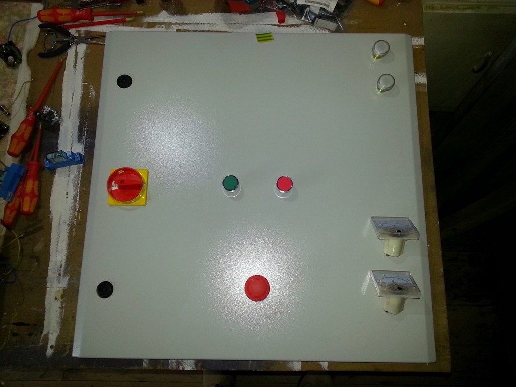
There were certain things that I knew I wanted. The e-stop button had to be on it’s own and easy to locate. The start and stop buttons needed to be close together but far enough apart they wouldn’t be triggered by accident and I wanted the dials down the bottom right corner as that just felt right. I initially tried it with the indicator lamps above the start and stop buttons but it didn’t work visually. I thought it would probably look even worse when the machine was powered up as I wanted the red light to indicate power was on but it would have been above the green button. The red stop button would have had the green ready light above it. Up the top right hand corner seemed like the obvious other location for the lamps and I’m actually really pleased with it now it’s all done.
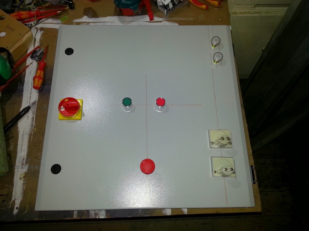
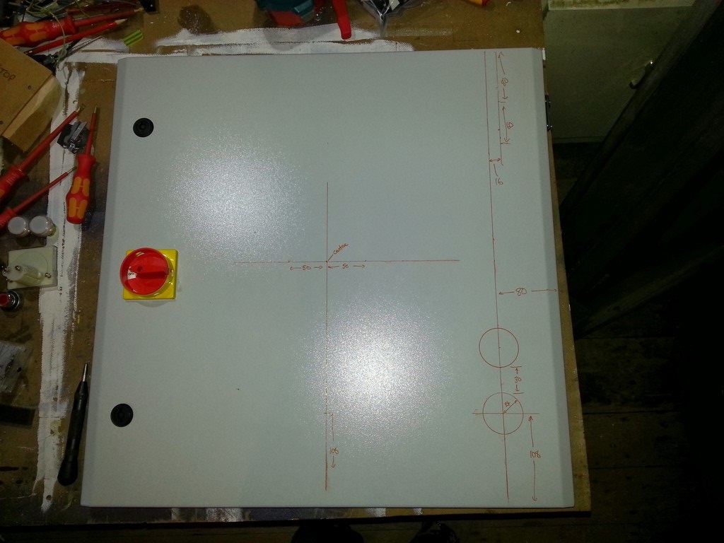
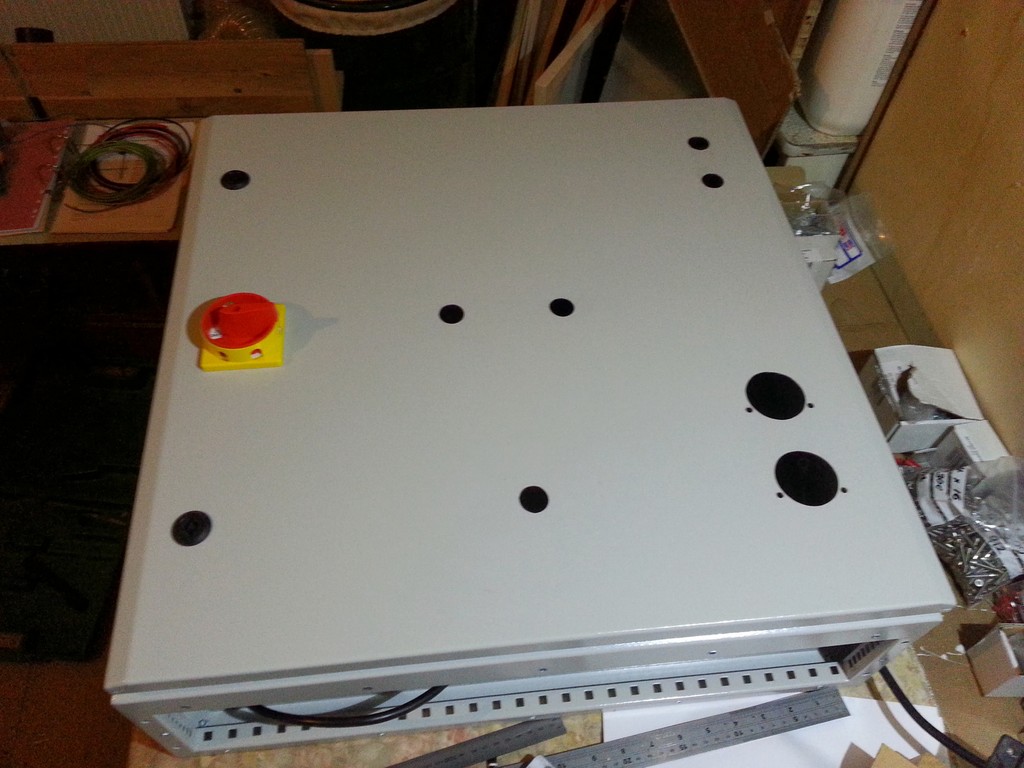
The second picture shows the start of the layout. I noticed that the indicator lights looked best if they lined up with the right of the dials. If they were on the same centre line the were too far from the edge of the door. Picture three shows the full layout with measurements to copy if you are following along at home.
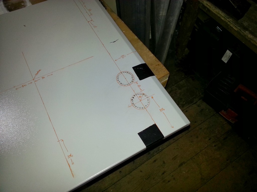
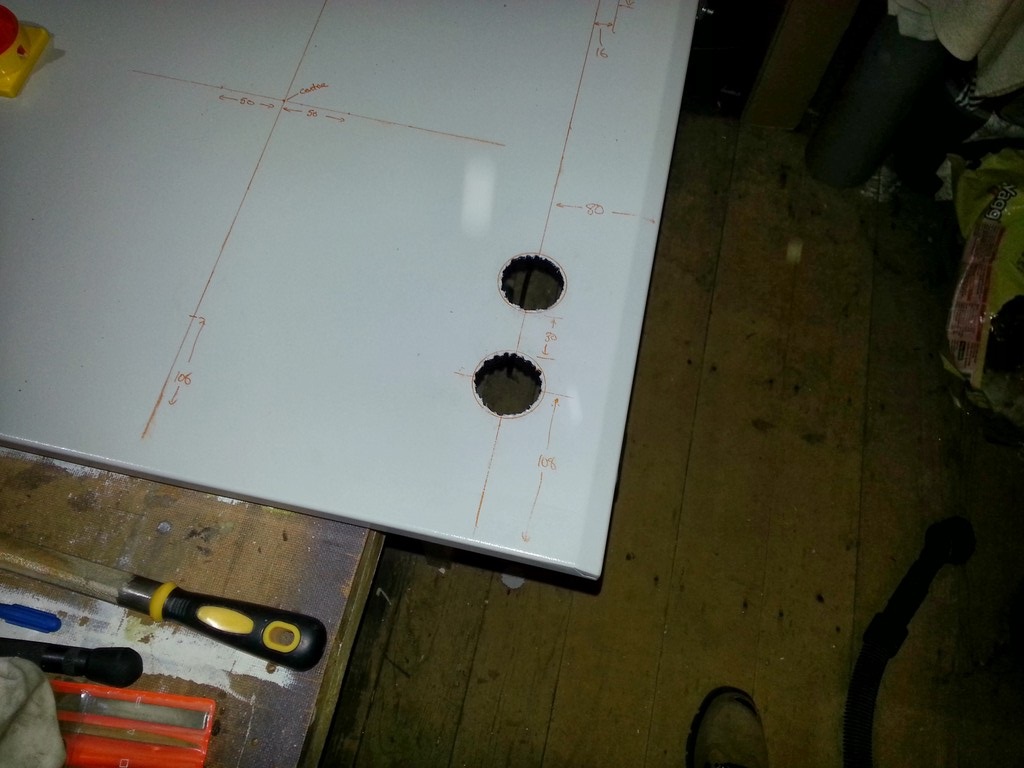
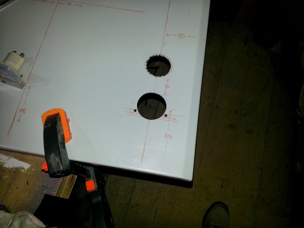
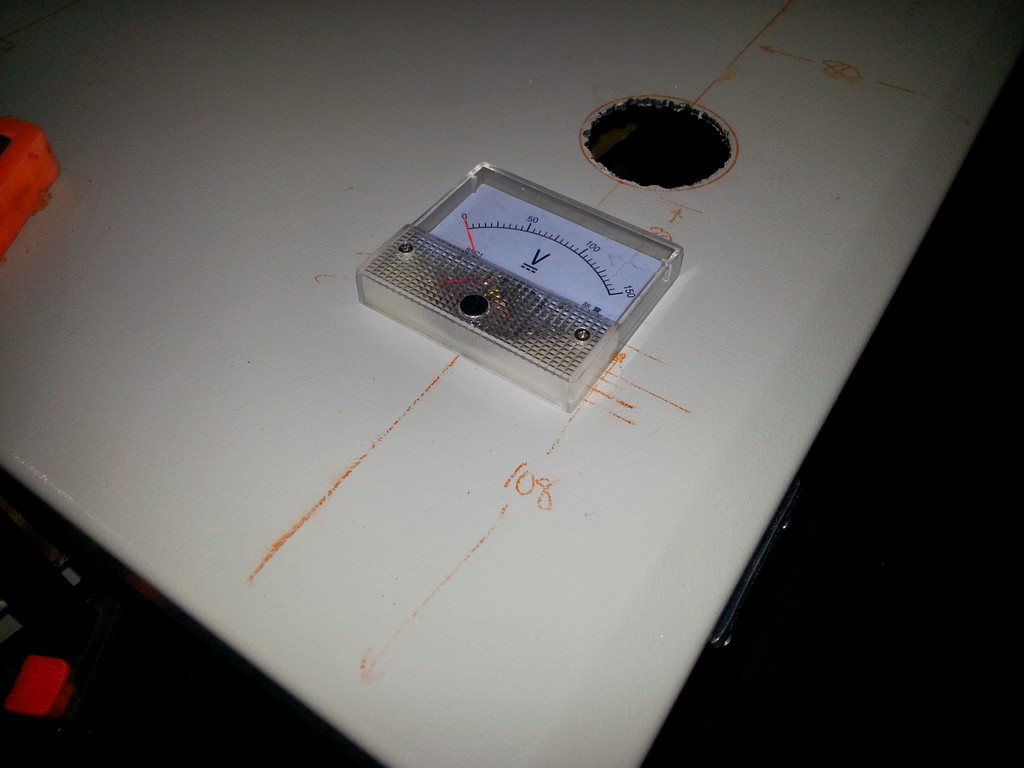
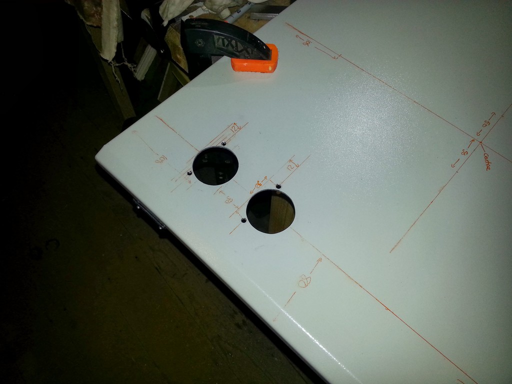
I decided to start with the holes for the dials as I figured they would probably be the hardest work and I certainly wasn’t wrong. Although I have a small pillar drill I have nothing that would cut a hole of the sort of size I needed here so my only option was chain drill, jig saw and file. After an absolute age of all three I finally had myself a fairly respectable looking set of mounting holes for the first dial. Being cheap parts from far flung lands they obviously don’t come with any diagrams for hole placement and measuring up for the location of the mounting bolts was awkward to say the least. They seem to be around 12mm (possibly 1/2 inch) up from the bottom of the dial. The bolts are M3 but come with washers that are more like M5 in diameter so you can drill the holes a little oversize to give some adjustment. No sooner had I fitted one I started on the next but boy was I fed up with filing.
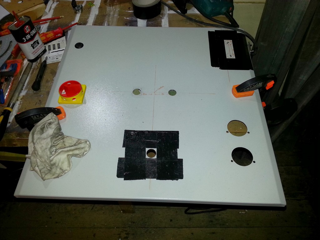
In an effort not to scratch the door while I was cutting out the holes with the jigsaw I put duct tape around the holes I was working on. I still managed to scratch the door slightly up by the indicator lamps though, as you’ll notice I didn’t tape up between the two holes which was a mistake. After about 5 hours of filing I eventually had all the holes completed and every thing fitting perfectly. I didn’t take any photos of the buttons and lamps but the connection mechanism is really quite clever. The part of the button you press is separate to the actual button mechanism and the two simply slot together with a quarter turn. There are then a couple of screws on the base plate that press the button to the case. That’s a terrible description but basically you don’t need any holes through the door to hold the button in place which gives it a really clean look, the only downside is it makes the parts quite chunky so make sure you have space in the case.
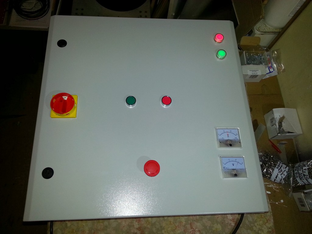
The next day I wired up the buttons, lights and dials which took almost the whole day. Everything is neatly wrapped and zip tied in place. Oddly I didn’t take a photo of the inside of the door at that point but I’m sure there will be one along later. I did take a photo with everything powered up for the first time though, notice the dials showing a 24V DC and 70V DC. I’m wishing I’d got a third dial now for the mains voltage, perhaps I’ll fit one if I need to order any parts of that particular supplier again.
It was at this point though I discovered a problem with my power supply. Way back in part two or three I mentioned that I was running it off an 8A fuse. Well that blew a couple of times which worried me as it was almost double the allowed current in the coil. I switched it out for a 6A Type C breaker which I found also tripped out on start up some times so I ordered a 6A Type D breaker thinking that would solve the problem. Unfortunately it didn’t and I continued to get the occasional trip. I went back and re-read the article on the power supply build and remembered what I’d written about inrush currents in transformer coils. It turns out I had under estimated quite how big the inrush current is, for a 1000VA coil it can be well over 100A and even pass 200A if the phase if just wrong. This sounds about right as a 6A Type D breaker shouldn’t instantly trip at less than 60A and will typically stay in for 80A or more. Note that this is an instant breaking current, a sustained current of a little over 6A should also trip the MCB. If the breaker stays in past the inrush it doesn’t trip so I’m happy the problem inrush not a basic flaw with the circuit. The solution it seems is to build a soft start circuit but that will be the subject of a future article.