
Now that everything is in the case and the control buttons are wired up it’s time to look at providing power to motors and get things turning. Before I rush into that though it’s time to correct and oversight.
So there I am all proud of myself for getting the 24V safety circuit wired up so that it controls the contactor and I think to myself, how long does it take for the power supply to become safe after I power it down? The issue with the power supply are the capacitors, I knew they held a significant amount of power which had to be bled away through a resistor what I didn’t realize was quite how much power they held. After a test power up I decided to time how long the power supply took to reach a safe voltage discharging through the one bleed resistor I had in place at the time. After the voltage had dropped from 70 to about 35V I got fed up and decided to probe the top of one of the capacitors to find out how accurate the dial gauge was. I must be thick or something…
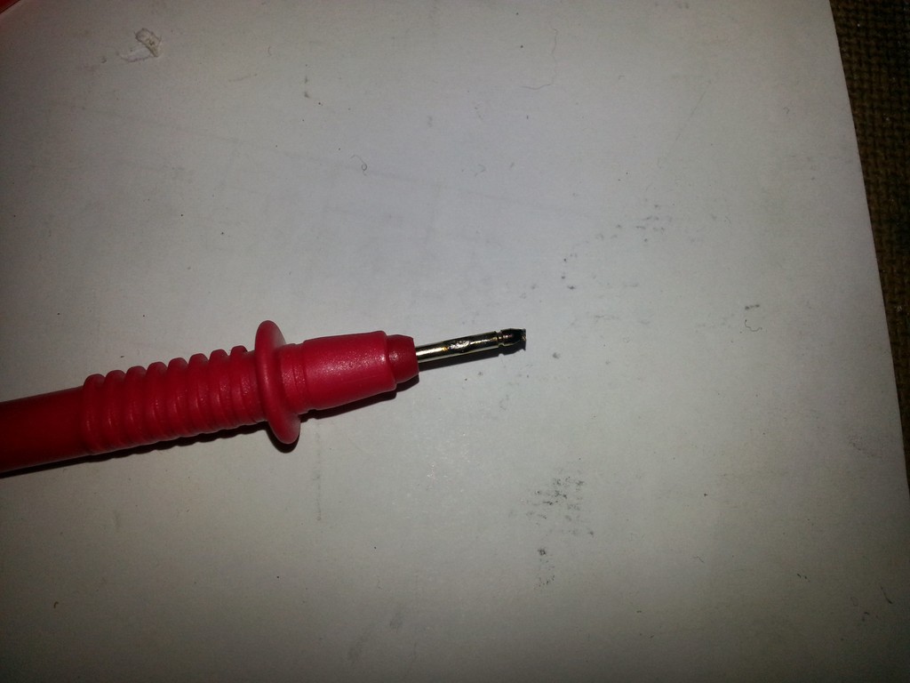
I was a rightfully scared of the capacitors so I was holding the probes further back than I normally would when the red probe slipped and shorted out the capacitor bank. In a blinding flash and loud snap the end of my probe vaporised. I quickly closed the lid and had a look at the voltage. To my amazement the voltage hadn’t really dropped – those capacitors still had a lot of power left to give.
Having had a glimpse of what could happen I decided it would be a good idea to fit an idiot guard to the power supply. I wasn’t looking to prevent every possible stupid scenario you could think of just the most common “ooops I’ve blown my finger off” type scenarios. My thinking here is that once the case is finished neither I nor anyone else will be going anywhere near the insides when it’s live. While I’m building the case though I don’t want to get fried. If you were determined to get yourself electrocuted you could but if that’s your goal there are other easier ways then inside this case.
The first problem I had was deciding how to make the power supply safer. Clearly it needed some sort of cover and ideally fitting / removing that cover wouldn’t require major surgery to the rest of the installation. The best solution would be to attach the cover to the case and have it float above the power supply but that wasn’t going to happen. The power supply is a few millimetres above the return for the door and attaching it to the sloped part of the door area would be quite difficult, it would also leave the far corner of the cover unsupported and weak.
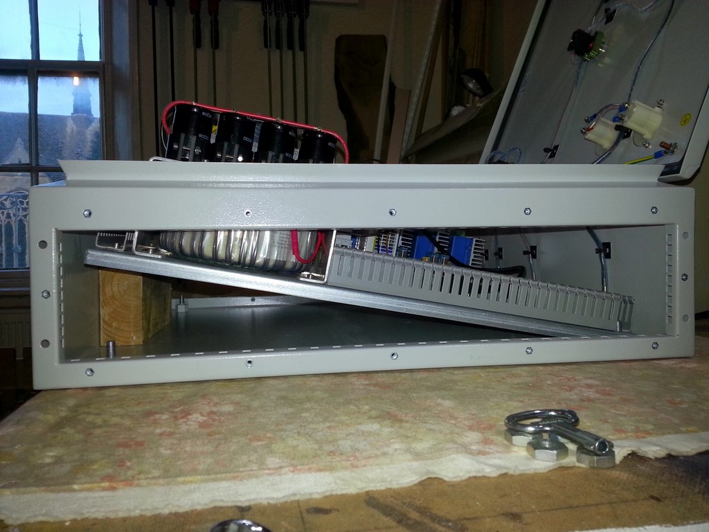
The only option therefore was to mount it to the power supply itself which meant fitting brackets to the power supply frame and this meant taking the panel out again so that I could get to the bolts for the power supply frame. There’s a problem with taking the panel out though… all the door switches, dials and lights are wired into components on the panel. Thankfully I realized the panel would tilt up quite a long way before binding on the mounting studs, enough in fact that I could slip in a bit of 2×4 which gave me just enough space to get my hand in and undo the nuts holding the power supply frame in.
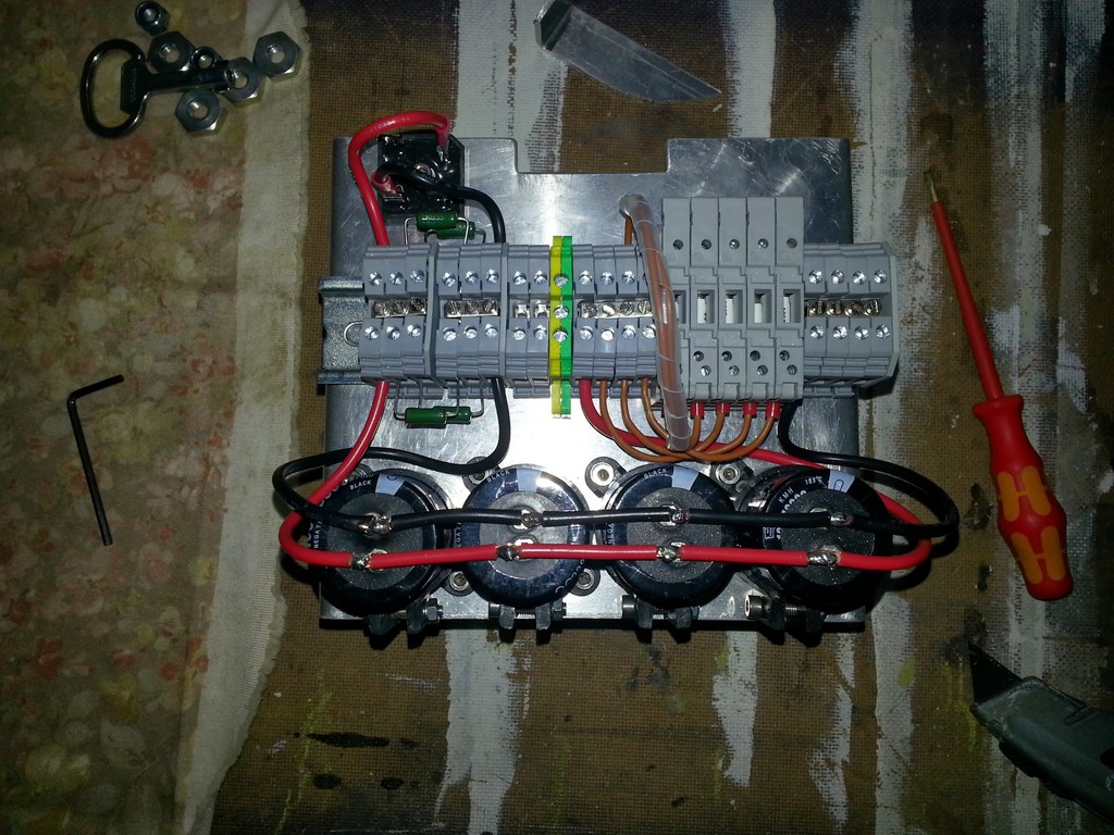
I forgot to take any up close pictures of the power supply build so here’s one. Note the DIN rail across the centre and the bridge at the top left. The capacitors are wired in parallel by stripping a little (5mm or so) insulation off some 2.5mm^2 cable and sliding it down on to the pins of the capacitor. A blob of solder then holds it all in place. I’m not over the moon at this connection method but it works and it certainly beats trying to make up a board or some other such mounting system. You can also see the bleed resistors on the left. These won’t be staying like this, I thought it was a good idea while I was designing the power supply but I’m not happy with them like that. They are only dissipating about 0.5W each so heat isn’t a problem I just don’t like the amount of bare metal they show.
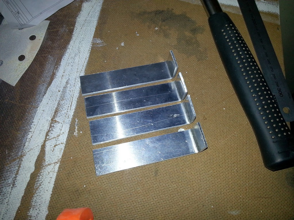
The solution I hit upon for a cover was to make some brackets and bolt them to the side of the power supply frame. If they were bolted at the corners, as seemed the best place, there was no risk of them interfering with the coil. I cut a 25mm strip off the end of the aluminium I made the frame out of and bent some brackets into shape. Picture two is before I drilled the holes for the bolts. There’s one at the bottom of the long edge and one in the connecting tab. The only thing to watch out for is making the connecting tab so long it could touch the capacitor. With 20mm long tabs I’ve got a good 10mm of clear air between the bracket and the capacitor.
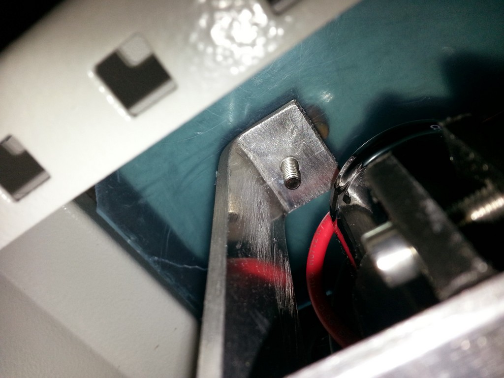
I got carried away at this point and forgot to take any photos but it was just a matter of drilling four holes in the power supply frame and bolting the brackets on. I then bolted the whole thing back onto the main mounting panel. The cover was made by just offering up the perspex and marking it in the where I wanted it to cover. I made it a little larger than the power supply to give bit of extra protection. Unfortunately I had to cut a hole in it for the door catch but this doesn’t fundamentally compromise the cover. I thought I had a good amount of clearance between the door studs and the cover but it turned out things were a lot tighter than I’d bargained for. As you can see from picture one it’s not clear whether the stud (brown) is hitting the bolt. The only way I could think to find out if there was actually space was to put a little ball of clay on the cover and let the stud make an impression in it. You can see in figure two that I’ve actually got about 5mm between the bolt and the stud although the stud has squashed the clay to about 1mm in thickness. Another lucky break.
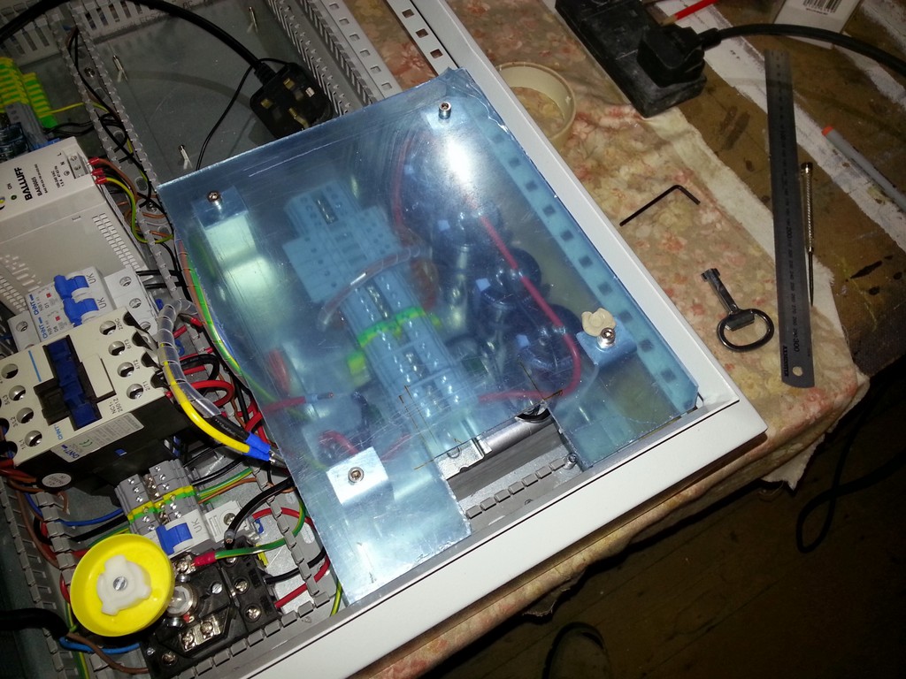
The last photo is of the cover in place. At the top of the picture you can also see some of the door wiring. This picture actually shows a little more than I intended at this point as I have a stepper fully wired in although I’ve not powered it up yet.