
I’ve received most of the electrical parts now so it’s time to start the build. The first thing to do is a dry run laying them out in the case.
Before I get into laying out the parts though here’s a couple of quick shots of the parts I’ve received so far:
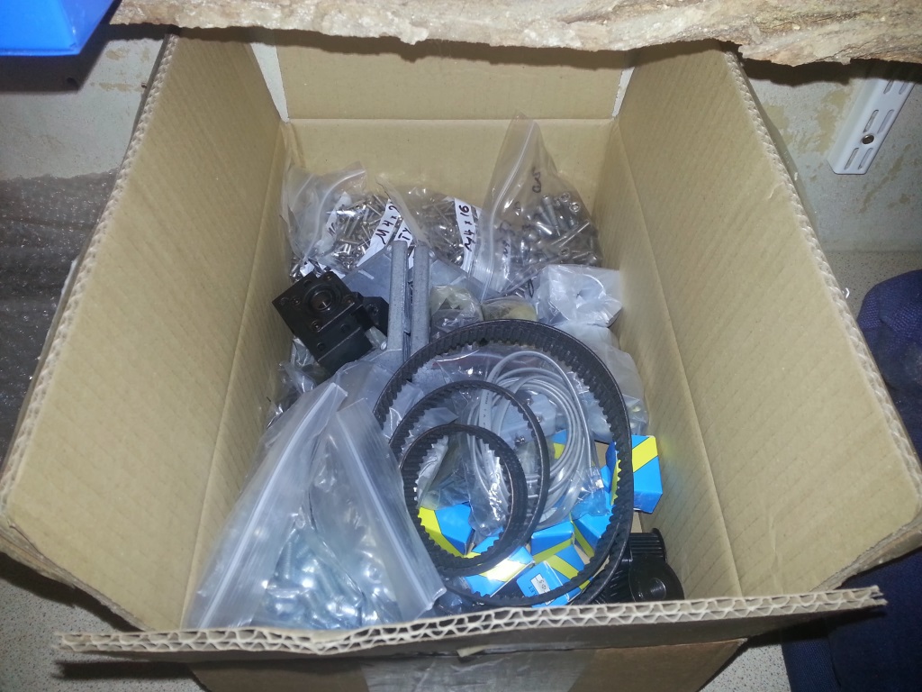
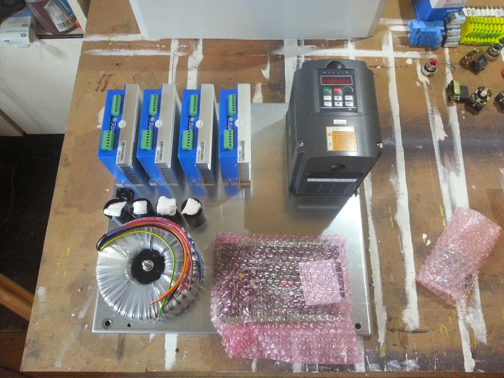
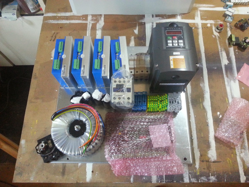
The first shows photo shows the VFD, drag chain, drivers, spindle and in the background the rails and screws. The box to the right is shown in the middle picture and contains all the mechanical parts such as bearings, mounts, bolts, etc. The picture on the right shows the electrical parts I’d received so far. I say so far because there was a bit of a mix up with my order and a big chunk of it was forgotten. A quick email sorted things out though and the parts arrived the next day so no harm done.
The first thing I did was open the case and marvel at the build quality, for the money I paid I’m really impressed. The mounting plate is good and thick and easily bolts into the case. The door has a good seal on it so no dust will be getting in and the door and end plates are easy to remove. If I had to pick fault it would be with the mounting plate mounting studs. Due to the location of the mounting holes you lose a good 3cm all around the edge of the mounting plate unless you can work around the holes and nuts. It turned out to be fairly easy to work around the holes so again, no harm done.The first shows photo shows the VFD, drag chain, drivers, spindle and in the background the rails and screws. The box to the right is shown in the middle picture and contains all the mechanical parts such as bearings, mounts, bolts, etc. The picture on the right shows the electrical parts I’d received so far. I say so far because there was a bit of a mix up with my order and a big chunk of it was forgotten. A quick email sorted things out though and the parts arrived the next day so no harm done.
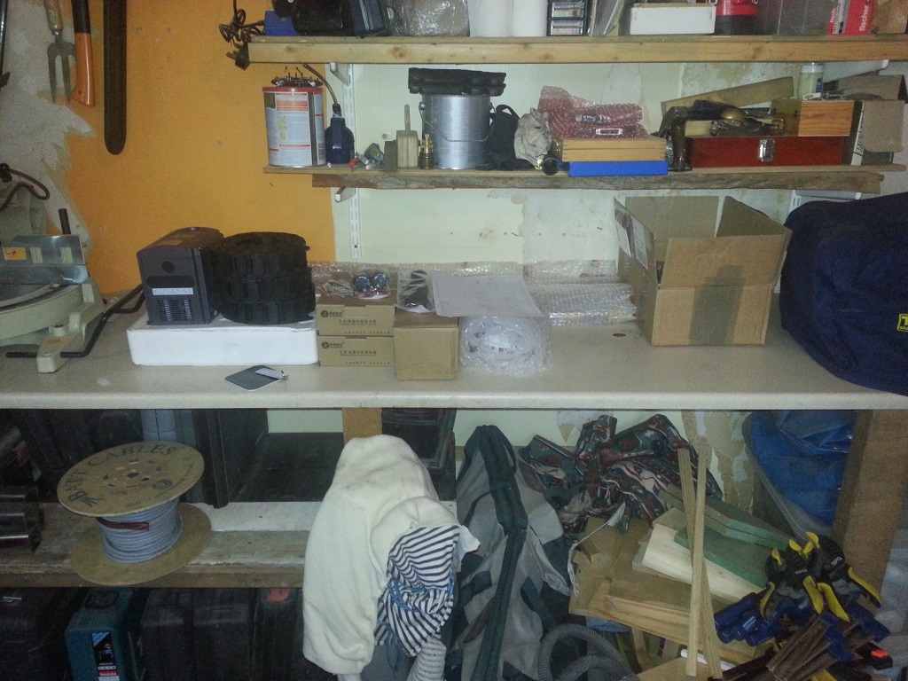
I initially bought a 500×500 case which gives a mounting plate of about 450×450. Before I bought the case I had very quickly laid a few of the parts out on my desk to make sure everything would fit and I was confident that I’d have ample space. I didn’t know how large some parts were so a full layout would have been difficult. The best I had to go on was a small photo of another build that was using many of the same parts. Anyway, it quickly became apparent that I wasn’t going to get everything into the 500×500 case as you can see from these two photos:
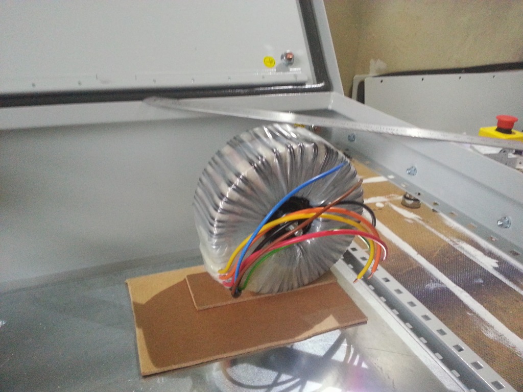
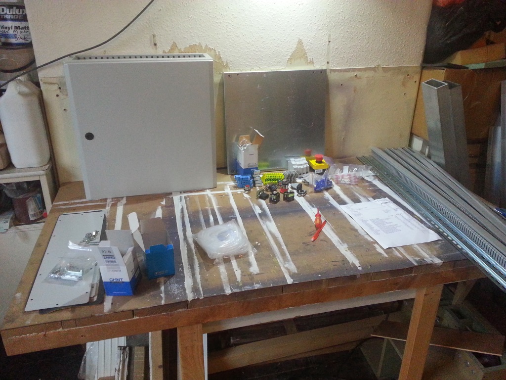
When I took the first photo I was thinking it was possible even if it was going to be very tight, by the second photo it was clear that there was no way it was going to all fit. Don’t forget that by this point I’d not even taken delivery of some parts that needed to go in the case. One thing did become apparent though, the power supply was going to be a pain to mount. The four capacitors are as wide as the coil meaning the bridge has to go on another row, this might not be a problem though as I need some connectors for the power supply anyway. In an effort to try and make it all fit I considered mounting the coil vertically. This would require me to make a strong bracket for it as it weights a good 6 or 7kg. The hard board represents the thickness of the aluminium that would make up the bracket, as you can see there is just clearance under the door.
Having realised it wasn’t all going to fit I started looking at the next size case up which was the 500×700. I quickly laid out the relevant space on the work bench in masking tape and dropped all the pieces in. The extra 20cm of height was a really big help but it was still surprisingly tight. The main problem was the width across the top where I wanted to mount five drivers and the VFD. Although I only have four drivers at the moment I’d like to make sure that I have the space to mount an additional one so that I can add another axis to the machine at a later date. The 500×700 case is just about wide enough as long as the drivers and VFD are below the mounting holes. The drivers and VFD should go at the top of the case as they will generate most of the heat; there’s no point heating up the BOB by putting it at the top.When I took the first photo I was thinking it was possible even if it was going to be very tight, by the second photo it was clear that there was no way it was going to all fit. Don’t forget that by this point I’d not even taken delivery of some parts that needed to go in the case. One thing did become apparent though, the power supply was going to be a pain to mount. The four capacitors are as wide as the coil meaning the bridge has to go on another row, this might not be a problem though as I need some connectors for the power supply anyway. In an effort to try and make it all fit I considered mounting the coil vertically. This would require me to make a strong bracket for it as it weights a good 6 or 7kg. The hard board represents the thickness of the aluminium that would make up the bracket, as you can see there is just clearance under the door.
Since the 500×700 was being awkward I stepped up slightly to the 600×600. The extra width came in really useful and resulted in the very clean layout shown below:
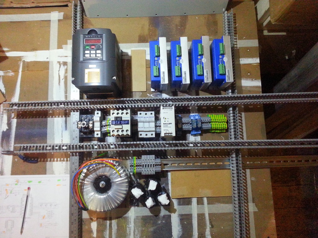
Bizarrely the layout is somewhat dictated by the door lock switch (left, middle). This has to be on the opposite side of the case to the hinges and it can’t interfere with the case locks (600mm high cases have two locks). The extra width means that the five drivers and the VFD all fit across the width of the case at the top. The layout shown here is intended to minimize interference by keeping all the high voltage, high power equipment and lines on the left hand side. Power will come in bottom left and then run up to the door switch. From there it will run to the VFD and coil and across to the 24 volt supply. The 70 volt supply for the drives will run up the left and across the top of the DIN rail. All the data lines will run up the right hand side and then across the top of the drivers as far from the power as possible.
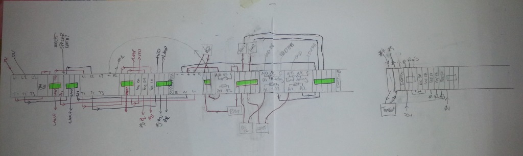
I’m really pleased with this layout even if it did take me the best part of a day to come up with. I had hoped to just bang din rails and parts into the case but it turned out to require some serious planning. As part of the process I had to draw a diagram showing the route of every wire. I hadn’t imagined how complex it would be to turn a wiring diagram into reality. For now I only have a paper version of the DIN wiring diagram I’m in the process of drawing it up properly and I’ll post it once it’s done but for now here’s what I have:Bizarrely the layout is somewhat dictated by the door lock switch (left, middle). This has to be on the opposite side of the case to the hinges and it can’t interfere with the case locks (600mm high cases have two locks). The extra width means that the five drivers and the VFD all fit across the width of the case at the top. The layout shown here is intended to minimize interference by keeping all the high voltage, high power equipment and lines on the left hand side. Power will come in bottom left and then run up to the door switch. From there it will run to the VFD and coil and across to the 24 volt supply. The 70 volt supply for the drives will run up the left and across the top of the DIN rail. All the data lines will run up the right hand side and then across the top of the drivers as far from the power as possible.
Although I probably don’t need to I’m going to build the mounting bracket for the transformer coil and mount it vertically. There’s no point taking up more space in the case than is necessary and the more free air I can give around things the better. I’m hoping a vertical mounting of the coil will also make laying out the capacitors a little easier. The only down side of this design is that it places the VFD on the left, away from the hinges. I had hoped to unclip the VFD controls and mount them in the door which will be tricky from this location. In reality I think once the VFD is set up for the spindle there won’t be much call for accessing the VFD control panel as the speed will be controlled by the computer. Either way I would have needed to make / buy an extension wire for the VFD control panel as the one it comes with is barely long enough to get the panel out.