Ironically the rollers, which I thought would be quite simple, turned out to be fairly difficult to get right. The problem I faced was similar to the problem I faced with the tensioning system – the bar or perhaps my drill bit didn’t seem to be quite the right size. Unlike with the tensioning system though I desperately didn’t want to alter the size of the bar so that meant altering the holes in the rollers.
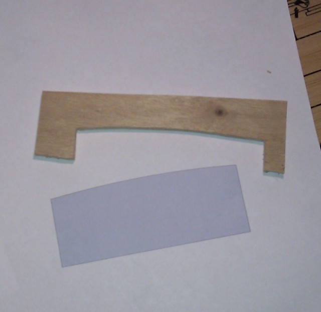
So the first thing I did was fire up SketchUp and knock out a design for the roller. I tried to look up a figure for how much crown to put on the wheel. The best I could come up with was 1/8 inch per foot for bandsaw wheels. That works out at just under 1.5mm per 100mm which I figured was probably impossible for me to turn in MDF without building jigs which I wasn’t about to start doing. As such I produced a design with 3mm of crown across 110mm. I then printed the design 1:1 and traced it onto a piece of 4mm ply with a knife. A quick bit of jigsaw action later and I had a wooden template to work too.
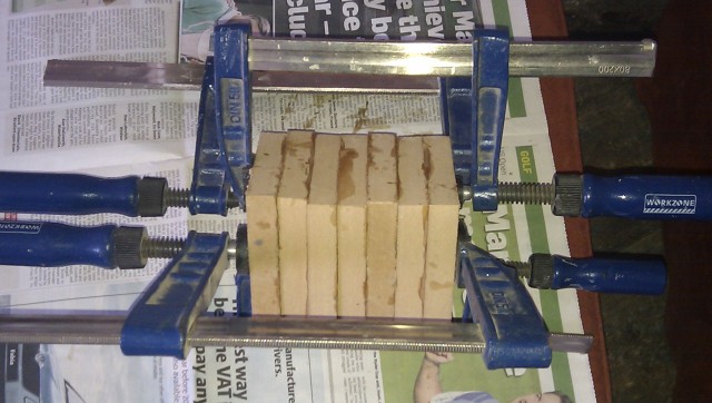
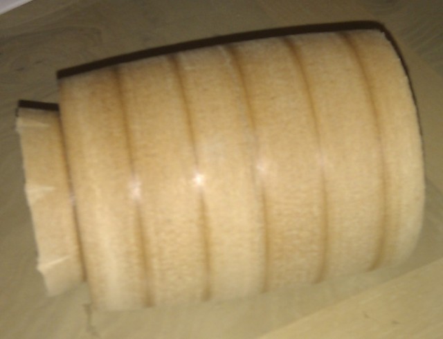
I decided that MDF was probably the best material I had available to make the wheels out of. Clearly it was going to be murder to turn to shape but at least it is a uniform density so there shouldn’t be many problems with vibrations due to the wheels being out of balance. I cut 7 blocks at 95mm square for each wheel and glued them together with Titebond III. Gluing them together was easier said than done – slippery little beggars.
I turned the block round, crowned it, added a chucking point and then coated the roller in sanding sealer to toughen up the lose internal fibres a little. I changed the procedure a little for the second roller as I didn’t crown it until after I’d reverse chucked it. My shaft metal is 20mm and I didn’t happen to have a 20mm auger – I thought I did – so I drilled out the first roller at 19mm hoping I could force the shaft in. It wasn’t going to happen and I couldn’t come up with any plan on how to make the hole bigger by a whole 1mm.
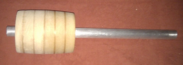
The next day I sent LOML out in the snow to buy me a 20mm auger :-). I re-mounted the roller on the lathe and bored out the hole to 20mm. Annoyingly the shaft still didn’t quite fit but it was very close so I turned up a 200mm length of dowel at 18mm wrapped a bit of 80 grit paper around it and by hand spun the roller around on it. After a few spins I was able to get the shaft into the roller. Interestingly the second roller went smoothly onto the shaft without the sander paper treatment, odd because the shaft measures as the same size.
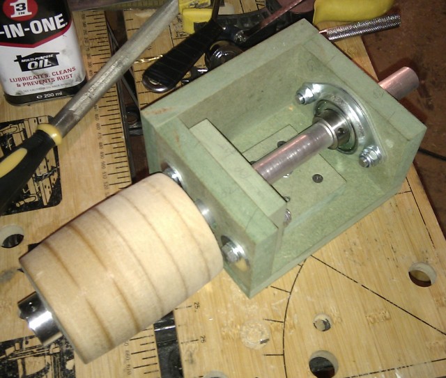
Most belt sanders have the idler shaft fixed with bearings in the roller but the design I’ve gone for requires the idler shaft to rotate so I need some way of locking the roller to the shaft. The plan I came up with was to drill a 5mm hole through the shaft and tap in a 6mm bolt.
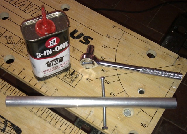
I started off trying to tap the hole all the way through using just a single bolt. I don’t have taps so I made a sort of tap out of a 6mm bolt that I put a cut in and got started. Amazingly I managed to tap all the way though the 20mm bar but as I was removing my home made tap it snapped in the shaft! All was not lost as luckily it snapped such that I had about 5mm each end in which to screw a bolt which is what I did. I then sawed the heads of the bolts so that I had 10mm or so sticking out each side. For the second shaft I didn’t bother tapping the hole first I just screwed bolts in. In hindsight I should have gone with my other idea which was roll pins but that would have meant buying some and this project is over budget already.
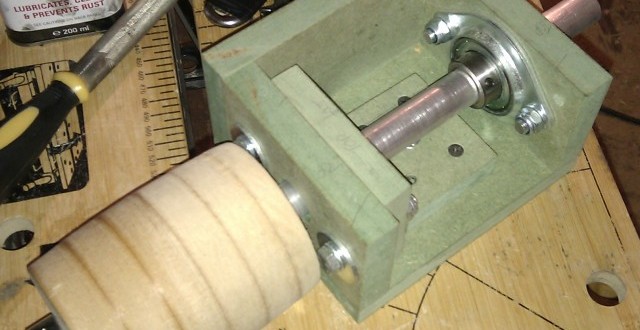
Finally I chopped out recesses in the roller to take the bolts and mounted it on the shaft giving me a completed idler stock.