As I mentioned at the end of the last part of this series I got the lamp to the point where it was built and I’d started testing but then gave up on the project. At this point I can’t even remember how to light one of the LED’s from the Pi so it’s time to get back to basics. I’m going to document every single step so that I, or you, can follow along.
How are Addressable LED Strips Different to Regular LED Strips?
With a regular LED strip, which is usually all white LEDs, you only get a choice of on or off for the whole strip. With addressable LED strips you get to choose both the colour and the brightness of every LED. This magic is achieved through the inclusion of a tiny micro-controller in each and every LED which can read instructions from a data channel built into the strip. The data can be supplied by a dedicated controller or from a programmable device such as a Raspberry Pi or an Arduino.
Lighting a Single Addressable LED
First things first, you need to make sure you know what type of addressable LED chip you are working with. The easiest way to find this is out is to look up what you bought, failing that you can try and compare what you have to pictures online. That’s not 100% fool proof but there aren’t that many common varieties. In my case I have WS2812b which is about the most common (I believe).
Understanding Power
I’m going to do something here that is not recommended, I’m going to power a small number (max five) of the WS2812b addressable LED’s directly from the Raspberry Pi GPIO pins. This is possible because the GPIO pins on the Pi include two pins (physical pins 2 and 4 – CAUTION: this is not GPIO pins 2 and 4) that are connected to the 5v rail, as shown on the pin out diagram here. The amount of current you can source from this pin is limited so don’t try and light up a whole string of LED’s or you’ll damage your Pi.
How much current can you source from these 5V pins? That’s a good question and it doesn’t have a single number answer. The top answer to this question gives a very good overview of the power capabilities of the Pi. To cut a long story short though, if you have a good power supply (I’m using a 3A Pi supply) and nothing else connected, you should be able to draw at least 1000mA from the 5V pin. The 5V rail is used to power the Pi and is connected to the power supply so, in theory, the current available is whatever the power supply can provide minus whatever is already being used. Personally, I wouldn’t push my luck sourcing power like this and I certainly wouldn’t try powering a motor from the 5V pins. Note, the 3.3V pins are much more limited as the 3.3V is generated on the Pi, apparently the community has tested them up to 800mA.
Connecting the LED Strip
The LED strip that I’m working with comes with 5 cables attached to one end, as shown in the picture below.
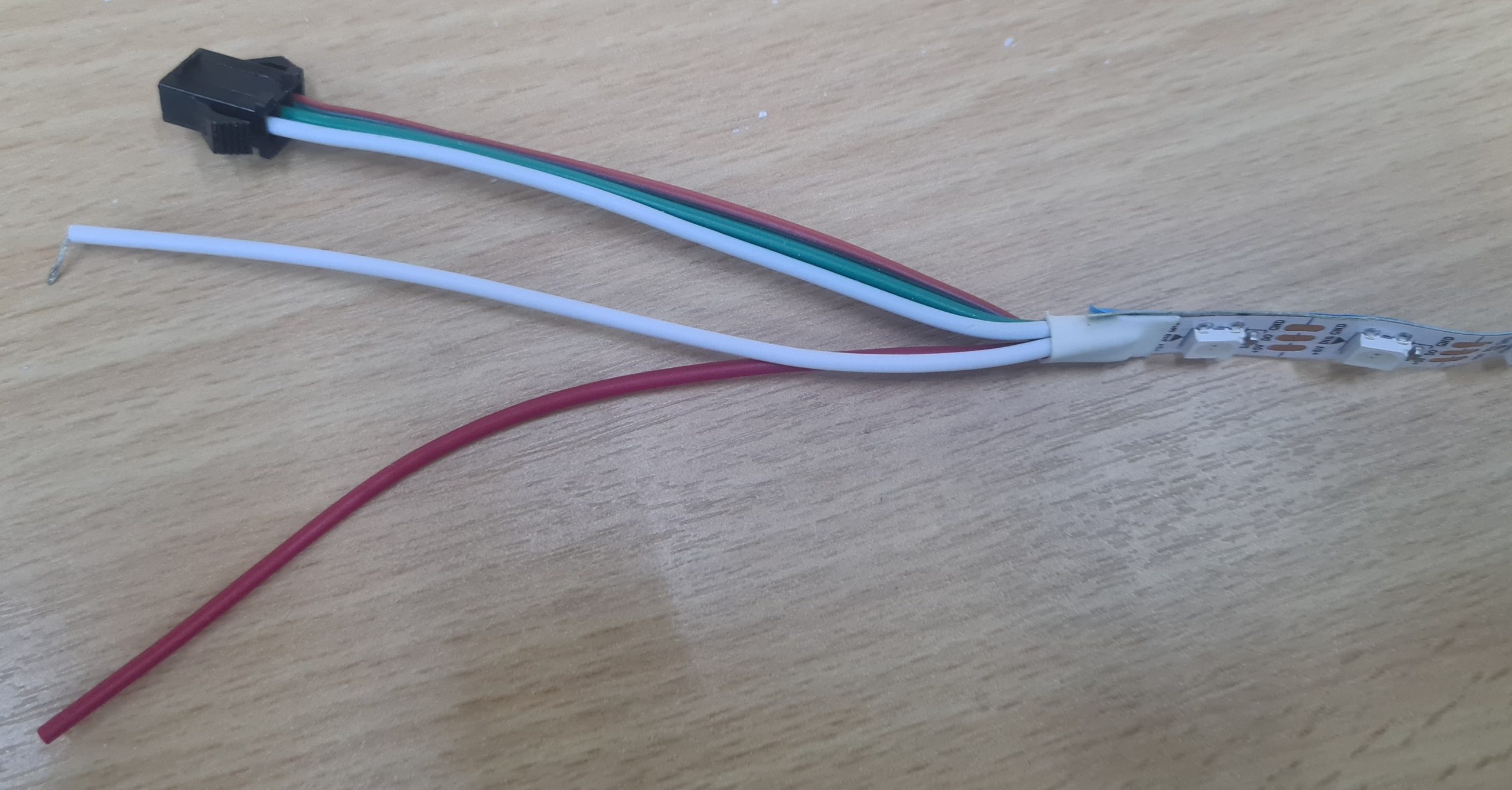
Red is for +5V, white is for 0V, and green is the data line. There are duplicate 5V and 0V lines so that you can provide separate power for the strip while still connecting all three cables to whatever is controlling the strip.
Since the Pi doesn’t have a socket that matches the connector on the LED strip I’ve just bodged some breadboard jumper cables into plug. This is obviously terrible but it’ll get things working for now.
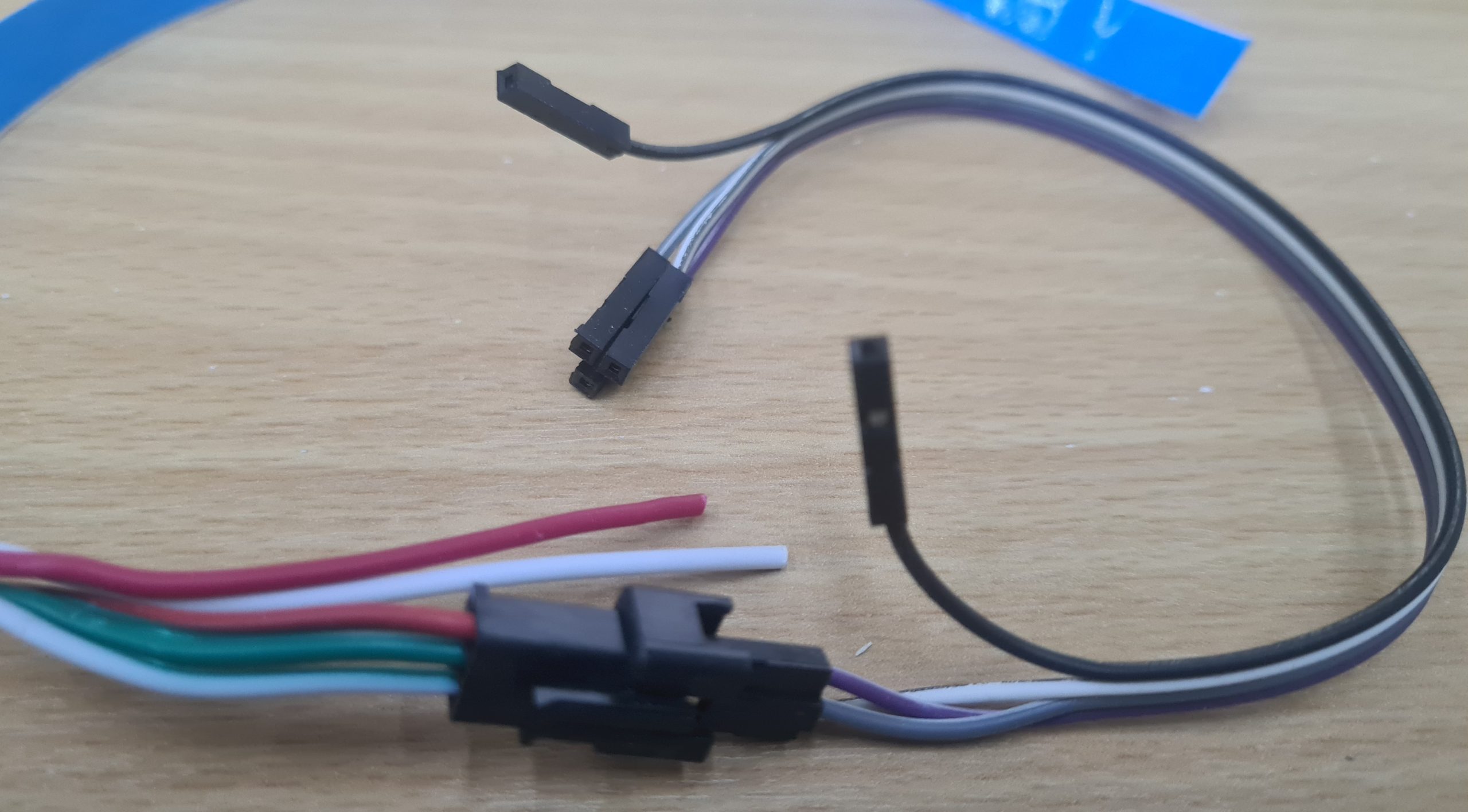
I couldn’t quickly find jumper cables that matched the colours on the LED strip so I have red going to purple (the most red like colour), green going to grey (both start with g), and white going to white (should be easy to remember). The black wire isn’t used.
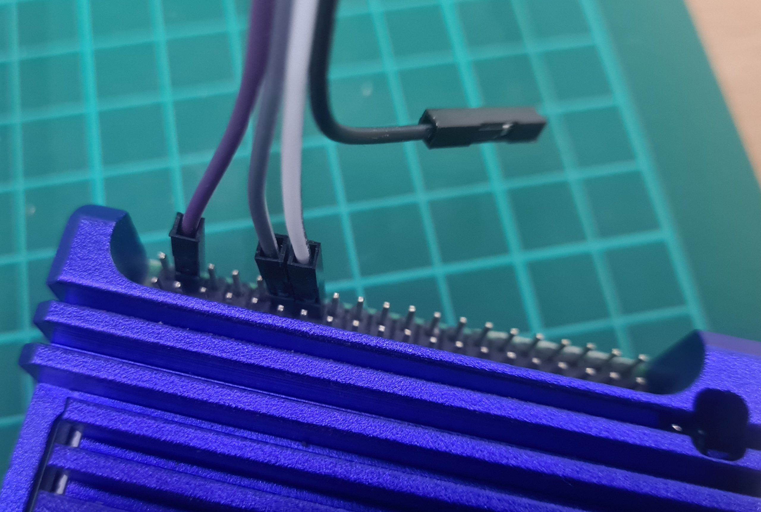
Connect purple to pin 4 on the Pi (5V), white to pin 14 (ground), and grey to pin 12 (GPIO 18) as shown in the photo below.
Important – Addressable LED Strips Have Direction
I scratched my head for about two hours trying to figure out why one of the test strips of LED tape I was using worked fine and the other one flat refused to ever show anything. The wiring was identical and I was certain the connections were good. Coming back to it the next day I decided to try buzzing it out with the multimeter to check for a bad connection, they were all fine except I got no continuity on the data line. That wasn’t a complete surprise, it does magic so there probably isn’t going to be a straight through connection. If you look carefully at the photos above you’ll notice that I switched the tape I was using because of this – in one photo there’s a plug and in the other it’s a socket.
In desperation I decided to start up a test application and then manually touch the data pin somewhere further down the strip (I’d verified I had power). My thinking was there might be a single bad LED at the end. Imagine my surprise when the LED that refused to work burst into life however it wasn’t the one I expected to start working. I expected the LED on the other side of the pad to start working. At that point it dawned on me. I had just assumed that the end of the strip with the socket on was the start but it’s not, it’s the end. The data only flows one way up the strip and I was connecting to the wrong end. If you look at the strip every LED has a little triangle pointing to it, that’s the direction of data flow.
If you’re wondering, yes, I do feel stupid. I’m surprised I’ve not seen this mentioned anywhere it seems like an easy mistake to make for a beginner. I’ve detailed the way I figured this out because I feel it was quite systematic and maybe someone that learn from that.
Writing Some Test Code
This is surprisingly well covered in a number of places so if I’m less than clear there’s plenty of other resources to check out. Start by installing the required libraries.
sudo pip3 install rpi_ws281x adafruit-circuitpython-neopixel
sudo python3 -m pip install --force-reinstall adafruit-blinka
Then, in your favourite text editor or IDE (if you are working on the Pi then you should have Geany installed) enter the following code.
import time
import board
import neopixel

pixel_pin = board.D18
num_pixels = 5
ORDER = neopixel.GRB

pixels = neopixel.NeoPixel(
    pixel_pin, num_pixels, brightness=0.2, auto_write=False, pixel_order=ORDER
)

while True:
	pixels[0] = (255, 0, 0)
	pixels.show()
	time.sleep(1)
	pixels[0] = (0, 255, 0)
	pixels.show()
	time.sleep(1)
	pixels[0] = (0, 0, 255)
	pixels.show()
	time.sleep(1)
step
This code won’t win any awards but it should make the first pixel cycle through red then green and finally blue. The line pixel_pin = board.D18 specifies the GPIO pin that the data line is connected to. The ORDER constant specifies the order that the library should specify the data to the pixels. The possible options can be found in the documentation for the Neopixel library here.
The line starting pixels sets up a pixels object that will be used to write to the LED’s. It has a number of options that can be set which are all well documented. The magic happens in the while loop (although that code is far from beautiful). The code sets the first pixlel to red then calls show which causes the data to be written to the LED’s. It then sleeps for one second before setting the first pixel to green and so on.
Running the Code
To run the code you need to open a command prompt and then enter
sudo python basics.py
Where basics.py is the name of the file you entered the above code into. The Neopixel library requires root privileges to access the GPIO pins. To stop the code press Ctrl-C. Note that the final pixel state will continue to display until you cut power to the LED’s this is just the way Neopixels work, they do what they were last told until told to do something different.
Well I think that wraps up this article. In the next article I’ll work on getting an independent power supply powering the LED’s. That will allow me to light more pixels and make them brighter without risking the Raspberry Pi.