In part 2 I got just a handful of LED’s running directly from the Raspberry Pi. That’s a little bit risky so in this article I’ll look at some other options for powering the LED’s.
Firstly…
It bugged me that the pixels would keep displaying the last state when I shut the application down (killed it more like). This can be fixed by using with as shown below.
... snip ...

with neopixel.NeoPixel(
    pixel_pin, num_pixels, brightness=0.2, auto_write=False, pixel_order=ORDER
) as pixels:

	while True:
		... snip ...
	step
I’ve snipped out the bits that didn’t change. I’m new to Python but I believe this is like a try with resources in Java, the with causes Python to clean up the resources when the application shuts down either cleanly or otherwise.
Using a Logic Level Shifter
The aim here is to decouple the power of the Pi from the power for the LED’s. Strictly speaking they don’t have to be separated. The Pi is powered with from a 5V supply and so there’s nothing stopping you from feeding 5V into the the relevant GPIO pins and not connecting the USB-C power connector. The problem with this approach is that it bypasses the current protection on the usual power connector – if you short your Pi like this it’ll catch fire 🙂
The data line of the WS2812b LED chips expects a voltage over 0.7V but if you want to get the signal to the end of a long line it’s probably better to use something like 5V and the datasheet always uses 4.5V to 5.5V on the data line in it’s examples. The data pins on the Pi are 3.3V so we need to use a logic level shifter to step the voltage up to 5V.
Level shifters are cheap and easy to get hold of. The one I’ll be using here came from eBay was was about £1.80 delivered in singles, I bought a pack of 10, I think that worked out about £1 each. They support four data lines and are bidirectional.
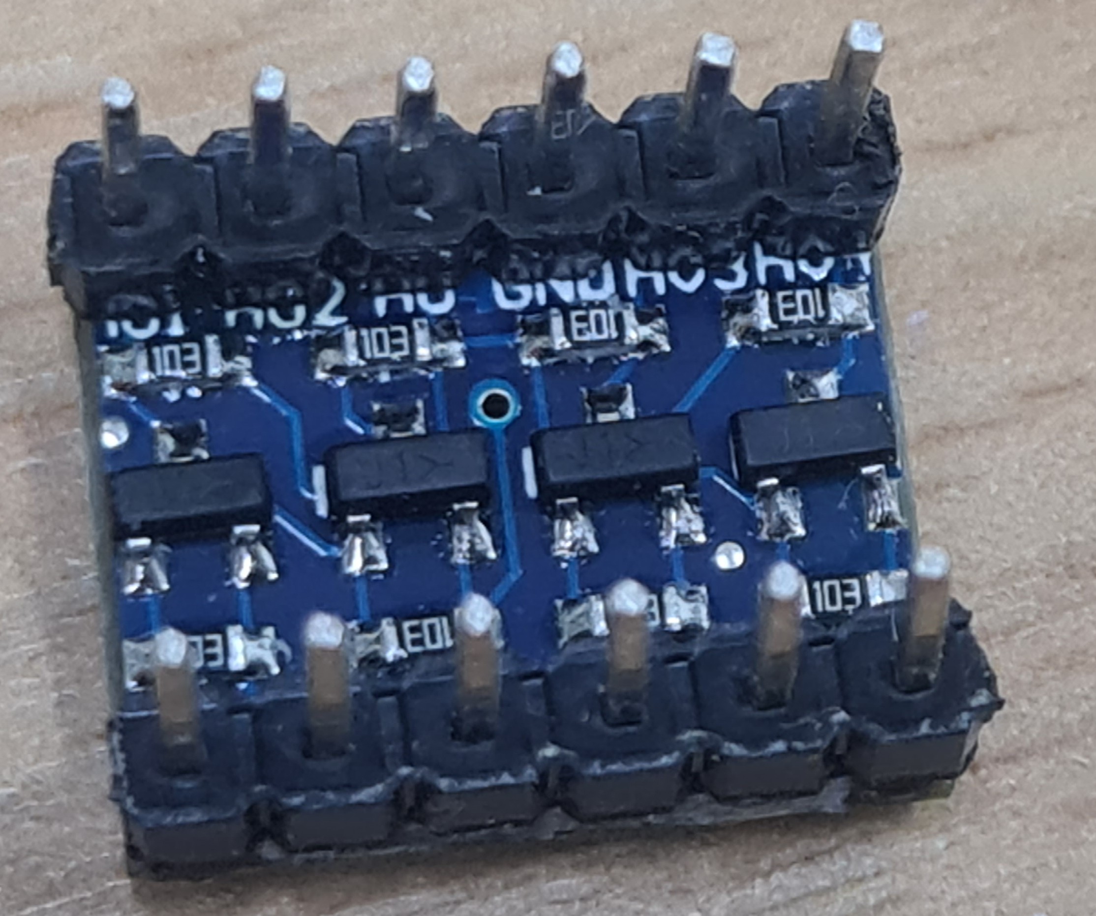
The silk screen is largely covered by the pins I’ve added to but across the top it says “HV1, HV2, HV, GND, HV3, HV4”. The bottom pins are labelled “LV1, LV2, LV, GND, LV3, LV4”. HV1 (high voltage 1) is connected to LV1 (low voltage 1) and so on. The HV and LV pins are for the high and low voltage references. The high voltage reference should be 5V and the low voltage 3.3V. Since the translation from high to low voltage is through a voltage divider I don’t think any other voltages will work. Note that you must not draw power through this device, it’s good for a few mA at most. The GND pins should be tied together and act as a common ground.
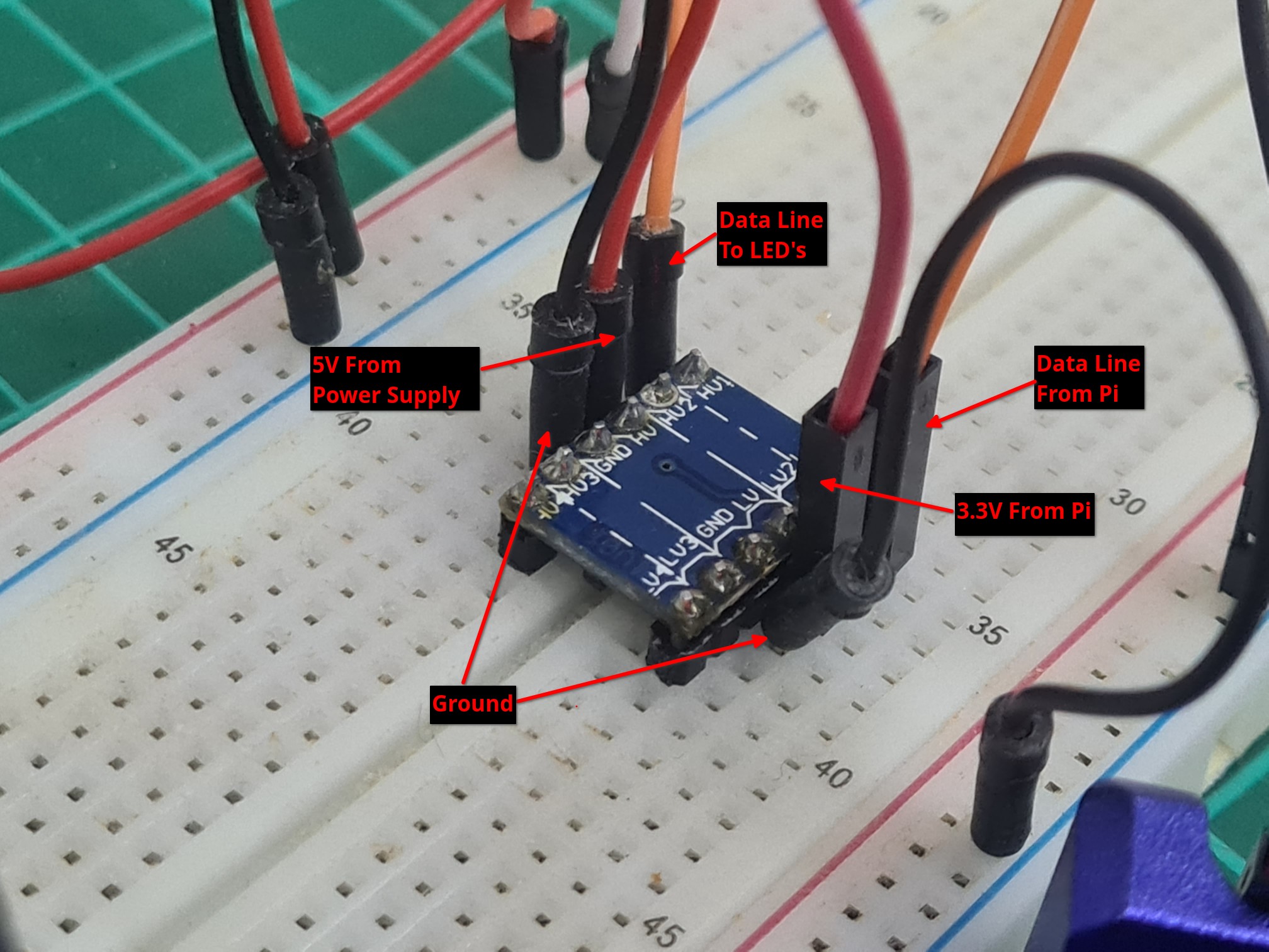
Wiring up is easy and to make things more obvious I’ve tried to stick to obvious colours in the photos below. Ground is black, except for the wire running to the LED strip which is white because the LED strip uses white for ground. All the positive voltage lines are red, whether they are 5V or 3.3V. Data lines are orange. When I find a decent circuit drawing app I’ll draw this out but for now here are a couple of photographs.
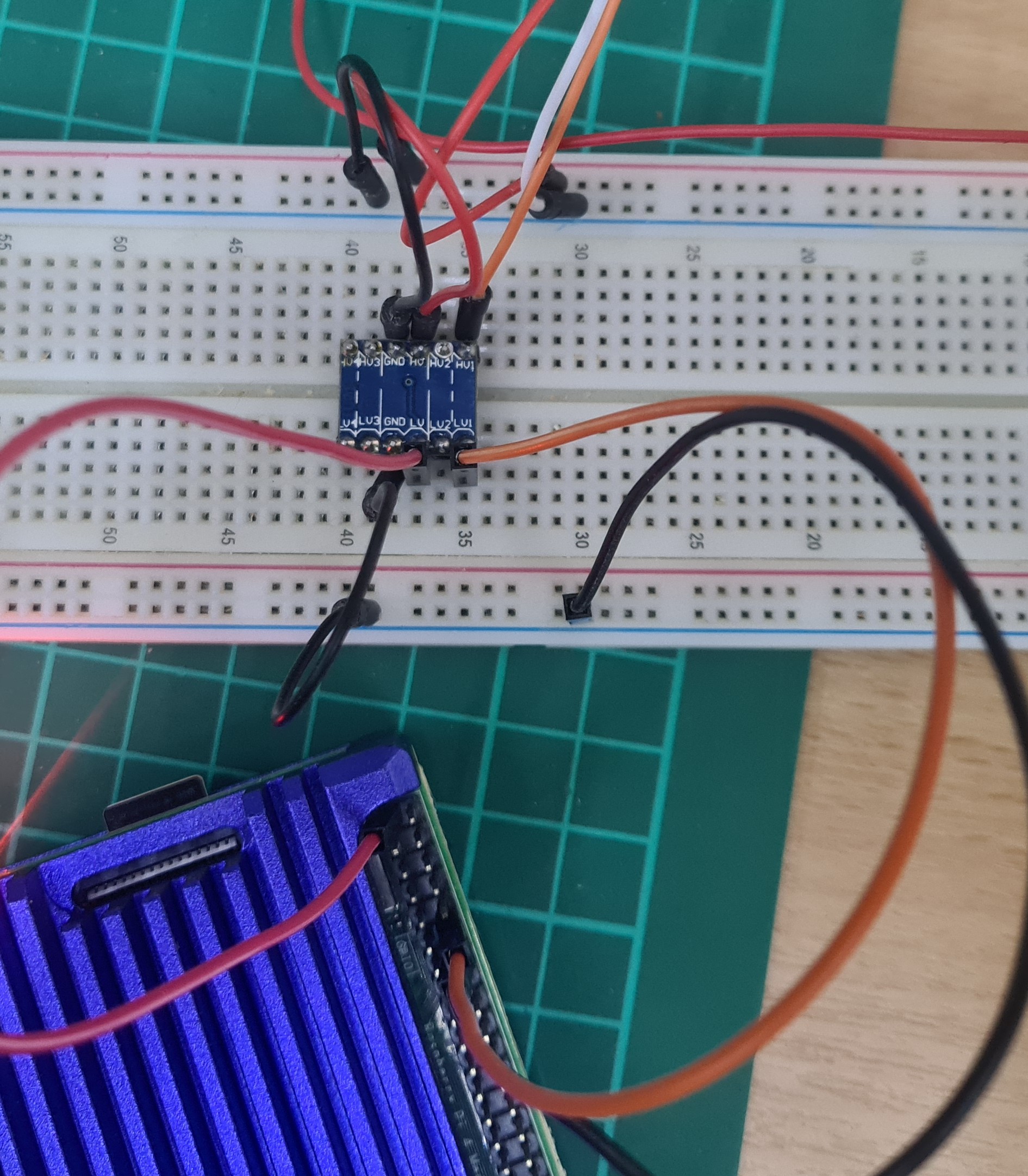
With that all wired up power it up and you should find that you can no control as many LED’s as you want (I believe there is an upper limit to the number of LED’s that can be addressed based on timing limitations). It’s time to move on to getting the lamp working again. The lamp is, essentially, just what you see above but bigger. The LED strip is 256 long and the whole thing is controlled by a Raspberry Pi Zero 2W.